How to Completely Test 3-Phase AC Induction Motors Using Deenergized Motor Testing
People often conduct motor inductance testing with methods that don’t accurately assess the whole picture. Inadequate testing can lead to premature equipment replacement, poor cost analyses and other negative outcomes. Deenergized motor testing with ALL-TEST Pro’s proprietary Motor Circuit Analysis (MCA™) devices can make testing more accurate, actionable and straightforward. This article will show you how to test a three-phase AC motor and explain why MCA™ methods are more comprehensive.
How Do Traditional Testing Methods Work?
Before we cover how to test a three-phase motor with modern testing procedures, we’ll review why traditional testing methods using insulation resistance to ground meters and multimeters typically aren’t enough. These tools overlook specific parts of the motor and won’t always help you tell if a three-phase motor is bad.
Insulation Resistance to Ground Meters
Evidence indicates only about 17% of electrical stator faults occur between the coils and the motor frame or are direct short to ground, while approximately 83% happen in the winding insulation. Since IRG testing ignores winding insulation, it only applies to a small percentage of faults. It also doesn’t assess the ground wall insulation’s overall condition, only its weakest point. IRG meters recommend using an antiquated polarization index to determine the GWI’s ability to store an electrical charge. These guidelines, based on older insulation types, can be invalid for newer insulation systems.
The purpose of IRG measurements isn’t to determine the insulation’s condition, but to verify that the three-phase electric motor is safe to energize. Additional measurements such as dissipation factor and capacitance to ground provide a more complete indication of the GWI’s overall condition.
Multimeters
Multimeters measure the resistance of the electrical circuit between specific motor leads. Theoretically, if the insulation surrounding the conductors breaks down (as in a winding short), the shorted coil’s resistance would be lower than the other coils, creating a resistance unbalance between phases.
The problem with resistance as an indicator of winding insulation degradation lies in the fundamental law of electricity that states the current takes the path of least resistance. Before the current can bypass a turn or turns in a coil, the insulation resistance between the coils needs to be lower than the resistance of the conductors of the shorted turn or turns. These values might be in the milliohms and usually aren’t measurable until the insulation between the windings is completely gone.
Another issue with multimeters is that insulation has a negative temperature coefficient. As its temperature increases, resistance decreases, potentially to a low enough value that the current would shortcut around the coil. If you take measurements after the motor has shut down, the temperatures of the winding and insulation have decreased, allowing the insulation’s resistance to increase enough for the current to follow its usual path and present with a balanced measurement between the phases.
How Does Insulation Break Down?
Assessing the condition of a three-phase motor relies on early indication of the insulation breakdown. To do this, MCA™ uses low-voltage AC signals to exercise the winding insulation system to determine when the winding insulation begins to undergo the chemical changes that occur as the insulation begins to degrade.
All matter consists of molecules and atoms. Atoms work like LEGO® bricks, forming molecules using chemical bonds. These bonds occur in an atom’s outermost shell (valence). Insulating materials have very tightly bonded valence electrons. Conductive materials have loosely bonded electrons in the valence shell. Heat can change the insulating material’s chemical makeup, causing the insulation surrounding the conductors to become more conductive and forming paths in the insulation. These paths create short circuits between the conductors.
According to the Arrhenius equation, these chemical reactions double for every temperature increase of 10 degrees Celsius. Insulation doesn’t fail instantaneously. All electrical insulation materials are dielectric and experience a change in chemical makeup over time, but these reactions hasten deterioration. Heat causes the reaction rate to increase, which correspondingly accelerates the deterioration rate.
When this happens, the insulation begins to fail in stages:
- As the insulation gets stressed, it becomes more conductive, less resistive and less capacitive. The temperature begins increasing in the fault zone, and the insulation forms carbonization paths. In the early stages, no current flows across the insulation.
- Resistance continues to decrease as the insulation degrades. Self-inductance and capacitance might decline, and the motor might start to trip intermittently but run successfully after insulation cools. Continued operation will allow temperatures in the fault zone to continue increasing as the fault worsens.
- Finally, insulation degrades until current flows across the fault zone. This phenomenon could cause a complete rupture of the winding insulation, vaporizing the winding. At this point, the coil’s inductance and winding resistance change.
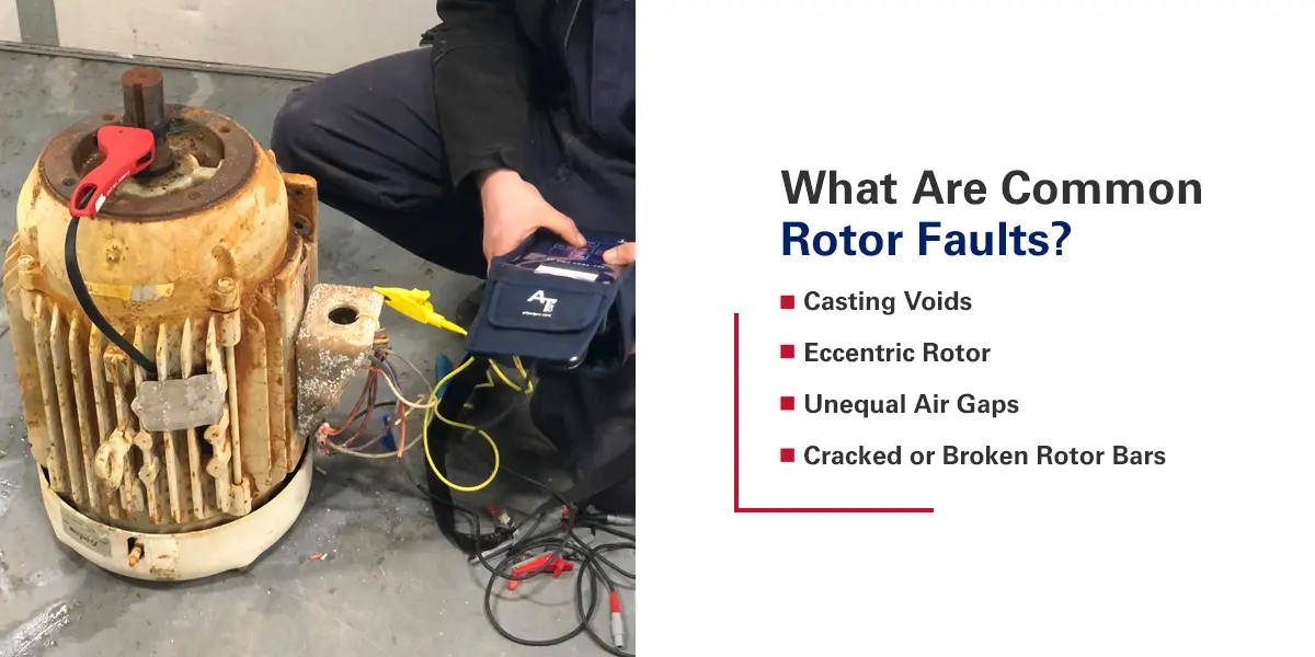
What Are Common Rotor Faults?
Some (EPRI states 10%) large three-phase AC induction motors fail due to rotor issues. These are undetectable in traditional motor testing methods or call for time-consuming diagnoses and complex testing instruments. Here are some typical rotor faults.
Casting Voids
Casting voids occur when vapor bubbles form in rotor bars or end rings in the electrical portion of the squirrel cage rotors. They increase resistance in the bar or bars. Rotor bars create parallel circuits. Basic electrical theory states that the voltage in each leg of parallel circuits is the same. A casting void in a rotor bar increases the resistance of the rotor bar, which causes the current flow (through the bar with the fault) to decrease, and it increases the current flow through the adjacent bars. The increased current flow through these adjacent rotor bars cause additional heating of these rotor bars. The additional heat causes the affected bars to thermally expand, causing the rotor to bow and creating excessive vibration and early and frequent bearing failures.
Eccentric Rotor
An eccentric rotor occurs when the shaft’s geometric centerline isn’t concentric with the rotor core’s geometric centerline. The point on the rotor that is farthest away from the shaft (high spot) will be closer to the stator, while the point on the opposite side of the rotor (low spot) will be closest to the shaft but will be farther away from the stator. Eccentricity creates unequal spacing between the rotor core and the stator core. Since an eccentric rotor has a high spot and a low spot, the unequal spacing between the rotor and stator changes with the rotor position.
This type of eccentricity is called dynamic eccentricity. This condition creates electrically unbalanced forces between the rotor and stator, which leads to frequent bearing failures.
Unequal Air Gaps
An unequal air gap occurs if a concentric rotor is not positioned in the stator field’s geometric centerline. This circumstance can occur due to imprecise, non-concentric machining of the rabbet fits on the motor frame and end bells. Even properly machined fits can allow the rotor’s GCL to be offset from the stator’s GCL. This issue creates narrow clearances and unbalanced electrical forces between the stator and rotor similar to an eccentric rotor, but the narrow clearance remains at a fixed location inside the motor and doesn’t change with the rotor orientation. This type of eccentricity is called static eccentricity.
A soft foot condition between the motor feet and base is a common cause of static eccentricity. If the motor’s feet are not in the same plane as the base that the motor mounts on, tightening the hold-down bolts on the motor frame can cause the motor frame to distort, which will also distort the stator field. These distortions create the same conditions as if the rotor were off-center in the stator magnetic field.
These air gaps can create narrow clearances and unbalanced magnetic forces that can lead to frequent bearing failures and cracks or breaks in the rotor bars.
Cracked or Broken Rotor Bars
Rotor bars act like conductors in the rotor electrical circuit. If the rotor bars are cracked or broken, dead spots will occur on the rotor when the affected bars are under any of the magnetic field stator poles rotating around the stator core. The current modulates through the rotor at a frequency equal to the number of poles in the motor and the frequency of the current flowing through the rotor. Broken or cracked rotor bars will prevent the rotor from achieving normal speed or creating excess current, heat and machinery vibration. If left uncorrected, the rotor can eventually self-destruct.
What Does Motor Circuit Analysis™ Entail?
To assess these rotor faults and the shortcomings of traditional testing, we can use more comprehensive Motor Circuit Analysis™ strategies to test a three-phase AC motor.
Ground Wall Insulation
Ground insulation is any insulation separating the electrical power supplied to the motor and frame or any other exposed portion of the motor. Its purpose is to direct the current’s path and prevent it from going anywhere besides its intended location. Remember, IRG measurements confirm a motor is safe to energize, not its condition. DF and CTG measurements provide more information on the overall GWI condition.
The GWI system can be modeled as a series-parallel RC circuit. The GWI insulation forms a capacitor since it is a dielectric material placed between conductive materials. The capacitor stores an electrical charge, so some of the alternating current applied to a capacitor returns to the source when you remove the voltage. However, some flows across the dielectric. The current that returns to the source is capacitive while the current that flows across the dielectric material is resistive. When you apply AC voltage to the capacitor, the capacitive current leads the voltage by 90 degrees, while the current that flows across the dielectric is resistive and in phase with the AC voltage.
New, clean insulation has a resistive current that’s 3 to 5% of the capacitive current. If the insulating material degrades, the resistive current increases or the capacitive current decreases or both occur. In any case, it affects the ratio of the resistive current to the capacitive current — the DF. An increasing DF indicates a degrading GWI, which could be from thermal degradation or contamination.
New, clean motors also have a specific CTG value. If the present value of the CTG has increased from the baseline, it usually occurs due to contaminated insulation or water ingression. Thermal degradation of GWI insulation increases the resistive current and decreases the capacitive current, so the CTG value decreases. Combining these two AC measurements with IRG measurements provides more information for determining the overall condition of the GWI.
Static Stator Winding Tests
Stator winding tests can be static or dynamic. Static tests occur when the rotor is stationary and include the following.
- Winding resistance: To measure winding resistance, you can sequentially apply a DC voltage to two of the three motor leads to assess the resistance of the conductors connected between instrument leads. Imbalances associated with winding resistance are usually due to loose or high-resistance connections.
- Inductance (L): Inductance measures a coil or winding’s ability to store a magnetic field. Motors have both self-inductance and mutual inductance. Degradation of a coil’s insulation affects self-inductance, and any change in the rotor’s electrical circuit affects mutual inductance. Inductance imbalance often comes from rotor position. Rotor position is not a problem but is a naturally occurring condition associated with induction motors. AC induction motors can be molded as a transformer with a rotating secondary. The stator windings act as the primary and the rotor bars are the secondary. In a static condition, the number of rotor bars positioned directly under the energized coils being tested establishes the turns ratio between the primary and secondary. This establishes the mutual inductance between the rotor and stator. If the number of rotor bars positioned under each phase are not the same due to rotor position, it will create an imbalanced inductance between phases.
- Impedance (Z): Impedance is the total opposition to current flow in an AC circuit. While resistance only measures DC opposition, inductance and capacitance in the circuit affect impedance. These quantities change when the insulation surrounding the conductors that form the coils of the windings starts to change. Since Z is a scaler value it can miss small changes in the early stages of insulation degradation.
- Phase angle (Fi): The phase angle measures the time delay between two or more events within the same period. A complete cycle is 360 degrees. If it takes one second to complete a cycle (the period of the cycle), and one event lags behind the other by half a second (half a cycle, or 180 degrees), the Fi is 180 degrees. Frequency is the inverse of time (1/T), so all events with the same period occur at the same frequency. If the cycles don’t start simultaneously, one will lead or lag. Resistive, inductive and capacitive circuits will differ in how current and voltage lead or lag each other. So when the chemical makeup of the insulation surrounding the conductors making up the coils begins to change, the Fi will change before Z, L, R or C. The Fi measurement is a leading indicator of insulation breakdown.
- Current frequency response (I/F): Inductors store magnetic fields to oppose a change in current, while capacitors store electrical charges to oppose a change in voltage. If these properties change, so does the coil or winding’s ability to store a charge or magnetic field. Insulation surrounds the conductors in the phase windings’ coils. If the insulations surrounding all the coils all have the same condition, each phase has the same storage ability. Once the insulation begins to degrade, this ability changes, creating an imbalance in the phase coils’ ability to store a magnetic field or electrical charge. The I/F response measures a coil’s ability to store a magnetic field or an electrical charge. Imbalances over 2% of I/F of any coil from the average of all phases indicate a developing fault in the winding.
MCA™ is a field-proven technology that has been used successfully in the field for over 35 years. MCA™ has documented guidelines to identify developing winding and rotor faults. To casual practitioners, these guidelines may be challenging to remember and apply. So, upon some users’ requests, ALL-TEST Pro’s engineers developed a unique and patented solution. They developed a proprietary algorithm combining all MCA™ measurements that defines the winding and rotor system’s condition. It provides a single value, the test value static. TVS™ doesn’t evaluate the insulation or rotor system’s fitness, but it reflects the condition of the motor’s winding and rotor electrical systems. Motors aren’t self-healing, so any change in the TVS™ indicates the motor’s condition is deteriorating.
The reference value static is generally the first TVS™ performed on a motor and is specified as the reference or “baseline” value. This allows the instrument to compare the results of any present “static test” to the stored RVS to evaluate the motor’s condition. The RVS is a TVS™ saved in the instrument or MCA™ software as a reference for comparisons. If the TVS™ changes by more than 3% from its original value, it’s an early warning. Past 5% indicates a severe change.
New or rebuilt motors should have the results of the first “static test” stored as RVS.
When a motor is first installed in a system, a new static test is performed from an easily accessible location like the motor control center or a local disconnect, and the results are stored as a new RVS. This new RVS incorporates all electrical components in the motor controller and associated cabling. Conducting any subsequent static tests from that location can quickly assess the electrical circuit’s condition.
If a new TVS™ differs from the RVS by less than 3%, the condition of the motor and associated components hasn’t changed. A warning past 3 or 5% indicates a developing fault or severe change, respectively. The change hasn’t necessarily occurred in the motor, but somewhere in the system. Isolating the fault calls for a new static test performed directly at the motor. If that TVS™ from the motor is within 3% of the RVS for the motor, the fault is in the controller or associated cabling. If it’s greater than 3%, the fault is in the motor windings or rotor system.
To determine if the fault is in the stator or rotor, you’ll need to perform a dynamic test.
Dynamic Tests
Dynamic tests take place while the motor shaft is smoothly, slowly rotating manually. They create a stator signature and rotor signature.
- Stator signature: The stator signature plots the mean values of change in impedance as the rotor bars move through the magnetic field created by energized coils. On good motors, the distribution of mean values is less than 1.1% from other phases. If it is higher, it indicates a developing fault in the insulation surrounding the conductors that make up the coils within the phases. If the values exceed a 3% change, severe degradation is occurring in the insulation.
- Rotor signature: The rotor signature indicates the amount each peak deviates from the mean value. On good rotors, these peaks are symmetrical. They should vary by less than 10% from other peaks in the phase. Between 10% and 15% indicates an early warning, and variation over 15% indicates a bad rotor.
Why Is MCA™ So Useful?
Unfortunately, a lack of knowledge about MCA’s™ modern, field-proven motor testing capabilities has limited the method’s widespread use. Traditional approaches have a limited ability to thoroughly analyze three-phase AC induction motors. Other time-consuming methods are available, but they still focus on the GWI, which does not provide any indication of the more common winding insulation and rotor issues.
There are more expensive instruments available that require more time to test but fail to determine the condition of the motor rotor or insulation system.
MCA™ overcomes these issues with an easy-to-use and understandable method of deenergized motor testing. It offers detailed, field-proven and accurate assessments for these three-phase AC motors. Our MCA™ instruments, like the ALL-TEST PRO 7™ and the ALL-TEST PRO 34™, are handheld, battery-powered tools that offer step-by-step instructions for performing the tests. They also deliver an immediate on-screen assessment of the motor condition.
Better, easier, faster motor testing with MCA™ can offer benefits like these.
- Increased accuracy and success in troubleshooting: Many motors have minor, often repairable faults, but their users discard them due to additional testing costs. Some plants replace troublesome motors over a predetermined size. By accurately identifying the fault, these users can perform better cost/repair analyses to reduce the number of replacements and minimize the costs associated with repairs, downtime and redirected skilled labor.
- More reliable installations: By inspecting new and rebuilt motors, a plant ensures they get what they pay for. You can avoid installing faulty motors or wasting motors that are still in good condition and easy to repair.
- Reduced downtime: Testing motors for indications of degradation can help you replace suspected or weak motors during a scheduled outage, instead of allowing sudden failures to stop operations and reduce your uptime.
ALL-TEST Pro’s MCA™ Equipment
Start using MCA™ and ALL-TEST Pro’s unique TVS™ and RVS values with our three-phase motor testing products. We offer an array of testing devices, and our knowledgeable team is happy to help you find the right one for your operation. Explore our devices online or reach out to us with any questions.
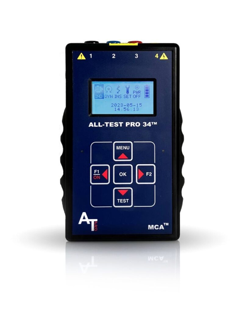
AT34™
Analyze and trend motor component integrity for ground faults, internal winding faults, open connections, and contamination – all with one hand-held device.

Motor Diagnostic Seminar at the University of Tennessee Reliability Center – Level 1 & Level 2 – July 22
The University of Tennessee Reliability Center and ALL-TEST Pro have teamed up to publicly present Motor Diagnostic Seminar Level I and Level II training courses this summer! This is a […]

Online World Class Motor Diagnostic Seminar – Level 1 – April 15-19
Have you heard? We will be holding our World Class Motor Diagnostic Seminar Level 1 on April 15-19. This will be an online/virtual seminar starting each day at 8AM EST. […]