WYE Start DELTA Run Motor Testing Using Motor Circuit Analysis
Frequently, when a process has a high inertial load, a six lead motor will be used as it can be connected in a WYE configuration while starting to limit current, and then switched to a DELTA configuration automatically by the motor controller once it has come up to speed.
Testing At The Motor Junction Box
As with many motors a simple way to test the six lead motor involves going directly to the motor junction box. After confirming that all Lock Out / Tag Out requirements have been complied with and the motor leads have been checked for the presence of voltage, the motor junction box can safely be opened.
If the motor leads from the controller and the internal motor wires are labeled, make note of that connection. If they are not marked then mark them with colored tape or other identification so that they can be properly reconnected when testing is complete. Disconnect the motor leads from the starter from the internal motor wires, or from the terminals in the box.
The internal motor wires or terminals should be numbered, one through six. As a check, you should be able to test for electrical continuity between terminals/wires 1-4, 2-5, and 3-6. These are your phase wires (A, B, C, or 1, 2, 3).
ATIV
To test the motor with an AT IV you can connect the instrument to terminals/wires 1-4 for phase 1, terminals/wires 2-5 for phase 2, and terminals/wires 3-6 for phase 3. All three windings should have the INS/grd test performed individually.
AT33IND or AT5
To test the motor in the WYE configuration you must short together terminals/wires number 4, 5, and 6. The wires can either be bolted together or significantly sized shorting jumpers used.
The tester(s) can then be connected to terminals/wire numbers 1, 2, and 3. Only one INS/grd test is necessary in this configuration.
Testing At The Motor Controller
There are many different ways to test six lead motor from the motor control depending on the size of the cables and the configuration of the control cabinet. In the cabinet pictured below, using an:
ATIV
At the bottom of the RUN and DELTA contactors do a normal test between 1-4, 2-5, and 3-6. Again, each winding should have the INS/grd test done separately.
AT33IND and AT5
The 4, 5, and 6 leads need to be shorted together. This can either be done with jumpers at the bottom of the DELTA or WYE contactors or the WYE contactor can be somehow forced. With this shorting accomplished the instrument can be connected to cables 1, 2, and 3 at the bottom of the RUN contactor.
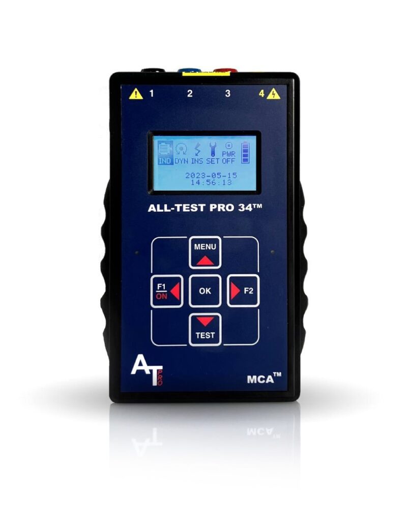
AT34™
Analyze and trend motor component integrity for ground faults, internal winding faults, open connections, and contamination – all with one hand-held device.

Motor Diagnostic Seminar at the University of Tennessee Reliability Center – Level 1 & Level 2 – July 22
The University of Tennessee Reliability Center and ALL-TEST Pro have teamed up to publicly present Motor Diagnostic Seminar Level I and Level II training courses this summer! This is a […]

Online World Class Motor Diagnostic Seminar – Level 1 – April 15-19
Have you heard? We will be holding our World Class Motor Diagnostic Seminar Level 1 on April 15-19. This will be an online/virtual seminar starting each day at 8AM EST. […]