What is dissipation factor?
What is dissipation factor?
Dissipation Factor is an electrical test helps defi ne the overall condition of an insulating material.
A di-electric material is a material which is a poor conductor of electricity but an efficient supporter of an electrostatic field. When an electrical insulating material is subjected to an electrostatic field, opposing electric charges in di-electric material form di-poles.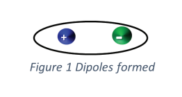
A capacitor is an electrical device that stores an electrical charge by placing a dielectric material between to conductive plates. The Ground Wall Insulation (GWI) system between the motor windings and the motor frame create a natural capacitor. The traditional method of testing the GWI is to measure the value of the resistance to ground.
This is a very valuable measurement for identifying weaknesses in the insulation but fails to defi ne the overall condition of the entire GWI system.
The Dissipation Factor provides additional information regarding the overall condition of the GWI.
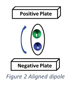
In the simplest form when a dielectric material is subjected to a DC fi eld the diploes in dielectric are displaced and aligned such that the negative end of the dipole is attracted toward the positive plate and the positive end of the dipole is attracted toward the negative plate.
Some of the current that flows from the source to the conductive plates will align the dipoles and create losses in the form of heat and some of the current will leak across the dielectric. These currents are resistive and expend energy, this is resistive current IR. The remainder of the
current is stored on the plates current and will be stored discharged back into system, this current is capacitive current IC.
When subjected to an AC field these dipoles will periodically displace as the polarity of the electrostatic field changes from positive to negative. This displacement of the dipoles creates heat and expends energy.
Simplistically speaking, the currents that displace the dipoles and leaks across the dielectric is resistive IR, the current that is stored to hold the dipoles in alignment is capacitive IC.
Dissipation Factor is the ratio of the resistive current IR to the capacitive current IC, this testing is widely used on electrical equipment such as electric motors, transformers, circuit breakers, generators, and cabling which is used to determine the capacitive properties of the insulation material of the windings and conductors. When the GWI degrades over time it becomes more resistive causing the amount of IR to increase. Contamination of the insulation changes the dielectric constant of the GWI again causing the AC current to become more resistive and less capacitive, this also causes the dissipation factor to increase. The Dissipation Factor of new, clean insulation is usually 3 to 5%, a DF greater than 6% indicates a change in the condition of the equipment’s insulation.
When moisture or contaminants are present in the GWI or even the insulation surrounding the windings, this causes a change in the chemical makeup of the dielectric material used as the equipment’s insulation. These changes result in a change in the DF and capacitance to ground.
An increase in the Dissipation Factor indicates a change in the overall condition of insulation, comparing DF and capacitance to ground helps determine the condition of insulation systems over time. Measuring Dissipation Factor at too high or too low temperature can result in unbalanced results and introduce errors while calculating.
IEEE standard 286-2000 recommends testing at or around ambient temperature of 77 degrees Fahrenheit or 25 degree Celsius.
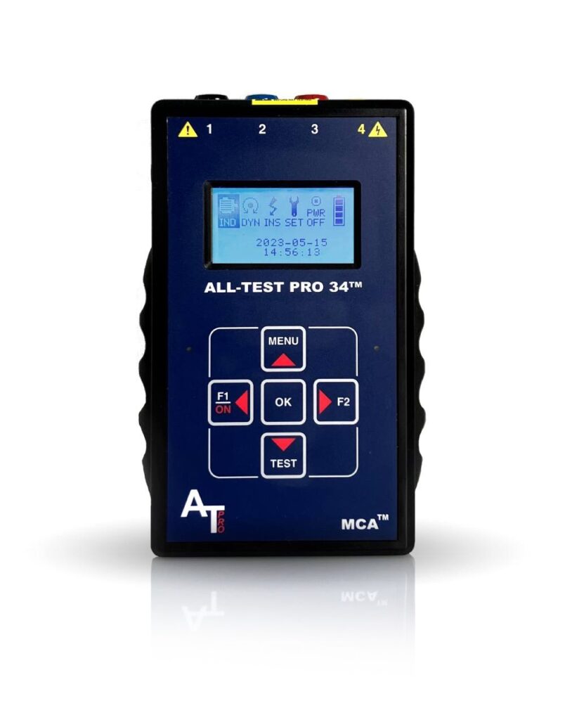
AT34™
Analyze and trend motor component integrity for ground faults, internal winding faults, open connections, and contamination – all with one hand-held device.

Motor Diagnostic Seminar at the University of Tennessee Reliability Center – Level 1 & Level 2 – July 22
The University of Tennessee Reliability Center and ALL-TEST Pro have teamed up to publicly present Motor Diagnostic Seminar Level I and Level II training courses this summer! This is a […]

Online World Class Motor Diagnostic Seminar – Level 1 – April 15-19
Have you heard? We will be holding our World Class Motor Diagnostic Seminar Level 1 on April 15-19. This will be an online/virtual seminar starting each day at 8AM EST. […]