利用电气特征分析检测脉冲宽度调制电机驱动器故障
The use of AC motor drivers in industry is increasing, and pulse width modulation (PWM) drivers have become the common industry standard for low-to-medium horsepower applications. Like other components within a motor system, PWM drivers have different failure modes, and electricians typically use digital multimeters (DMMs), digital oscilloscopes, and power quality analyzers to troubleshoot them. While these instruments do allow electricians to troubleshoot faults related to the input power supply and motor drive, their ability to detect faults in the motor itself and the motor-driven load is limited. Furthermore, because these instruments are independent, the reporting capabilities they provide may be limited, making predictive maintenance (PdM) or condition-based maintenance (CBM) testing difficult.
Compared to DMMs, oscilloscopes, and power quality analyzers , Electrical Characteristic Analysis (ESA) offers significant advantages in reliability testing. Furthermore, in addition to assessing the condition of the input power supply and motor drive, it also evaluates the condition of the motor and drive load to identify many common failure modes.
Regarding the European Space Agency
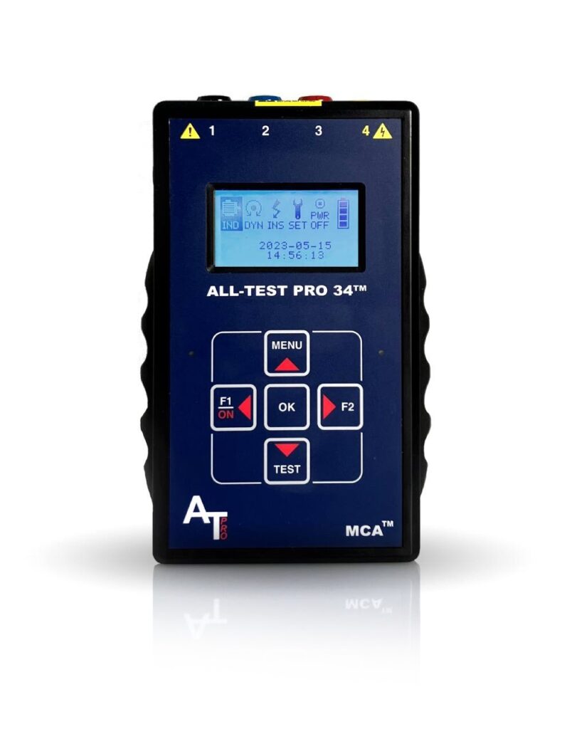
ESA is an online testing method that captures voltage and current waveforms while the motor system is running, and then performs spectral analysis in the provided software using Fast Fourier Transform (FFT). This FFT can detect faults related to the input power supply, control circuitry, the motor itself, and the drive load, and can also be used for trend analysis for CBM/PdM purposes. Our specialized ESA instruments are handheld, portable, and battery-powered.
All ESA analysis systems require the voltage, operating speed, full-load current, and horsepower (or kilowatts) information from the motor nameplate. Additionally, optional information such as the number of rotor shafts and stator slots, bearing part numbers, and information about the drive load components, such as the number of fan blades or gearbox teeth, can be entered for more detailed and accurate analysis.
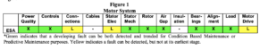
Since ESA is unfamiliar to many people, the following chart illustrates common faults detected by ESA. See Figure 1.
This article will discuss three common failures of PWM drivers:
1) The input diodes in the rectifier bridge are open.
2) Capacitor failure in the intermediate DC circuit.
3) Damage to the insulated gate bipolar transistor (IGBT).
Of these three types of faults, capacitor faults are the most difficult to detect early because they cannot be immediately detected by monitoring the motor’s performance.
About the driver
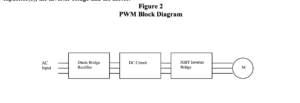
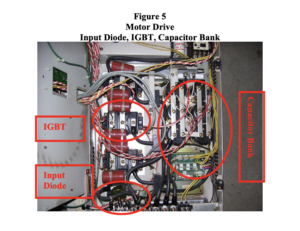
Figure 2 shows the basic modules of a PWM motor driver, including an input AC power supply, a full-wave diode bridge that rectifies the input AC voltage, an intermediate DC circuit containing capacitors, an inverter bridge, and a motor.
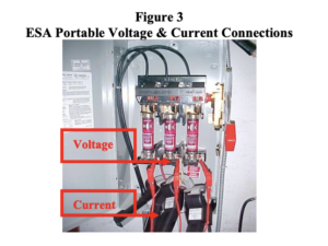
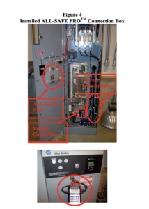
When using an ESA (Electronic Voltage Detector) for testing, voltage and current are connected to the motor system under test. Connections are typically made at the motor control center using a provided portable voltage probe and portable current transformer, or a pre-installed dedicated junction box. The advantage of a junction box is that it allows data acquisition without opening the motor control panel, thus enabling the necessary connections.
In PWM applications, two sets of data should be collected: one set at the input of the PWM driver and the other at the output. The entire data acquisition process (after connection is complete) takes approximately 4 minutes, during which time motor nameplate information is not required. This information can be entered later for data analysis.
Then use the provided software to view the data files and generate a Microsoft® Word report. This software offers easy-to-use tools for handling different analytical spectra. The software results can be viewed without generating a full report.
The software will automatically report the following information:
Power factor, current imbalance, voltage imbalance and voltage RMS value relative to nameplate, load relative to nameplate, phase connection, rotor health condition, stator electrical and mechanical health condition, rotor/stator air gap, total harmonic distortion (voltage and current), misalignment/imbalance indication and bearing health condition.
It can also report peak and peak current, phase impedance, power (apparent power, actual power, and reactive power), operating speed, and line frequency. For AC induction motors and DC motors, it can also calculate motor efficiency.
Even experienced users can perform a comprehensive analysis of each motor and generate a report within 10 minutes.
Case 1
Case number one involves a motor drive received by the EMA service center in Cortland, New York. The drive and motor were tested on a dynamometer.
Two sets of data were collected. The first set consisted of waveforms captured at the driver input, and the second set consisted of waveforms captured at the driver output. The second set of data included voltage and current waveform captures, as well as 50 seconds of voltage and current waveforms.
Figure 6 shows the input current waveform of phase C. This is caused by an open circuit in the diode.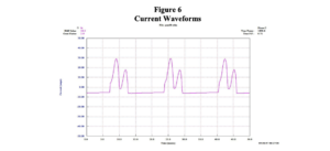
ESA’s automatically generated reports can identify current imbalances and excessive harmonic distortion caused by open diodes.
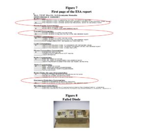
The first page of the report is just an abstract; several more pages provide detailed explanations of each main heading. As shown in the figure, high-current phase imbalance can damage the internal components of the PWM driver and may stress the power transformer feeding the motor driver.
Case 2
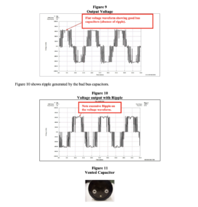
The second repair case received by the EMA involved aging capacitors in the capacitor bank. The problem was that the motor’s performance didn’t show any noticeable change as these capacitors began to age and fail. Once the capacitors started to fail, the good capacitors would carry extra current, generating excessive heat within them, which would accelerate the failure of the remaining capacitors. These capacitors had vents to release excess internal pressure, but if ventilation wasn’t sufficient, these capacitors could explode. Furthermore, excessively high ripple voltage supplied to the motor could cause harmonic currents to be generated. These harmonic currents would produce negative sequence torque, degrading motor performance and generating additional damaging heat inside the motor.
Figure 9 shows the voltage at the output of the driver, which is a good driver with the capacitor in good condition.
Case 3
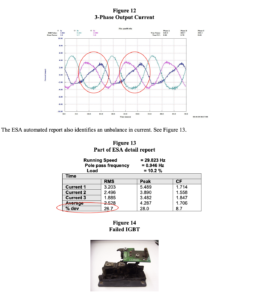
EMA received case number 3 requesting repair. The output waveform indicates that the IGBT (Insulated Gate Bipolar Transistor) is not turned on. This will cause current imbalance and waveform distortion.
Summarize
In summary, DMMs, oscilloscopes, and power quality instruments provide good troubleshooting capabilities for PWM motor drivers. However, they cannot be well integrated into motor reliability testing procedures due to limitations in data collection and reporting. Furthermore, they provide limited information on common motor and load-related issues.
Through electrical characteristic analysis, reliability technicians can examine the entire motor system, from the input power supply to the driven load. In PWM applications, data acquisition time is no more than 4 minutes after connecting voltage and current. This 4-minute test process allows for the rapid detection of issues such as rectifier diode failure, DC bus capacitor malfunction, and IGBT failure before a drive or motor fault leads to system failure.
It is worth noting that in all three scenarios, the motor may still be running, depending on the load and other operating factors, but the certainty of continued system operation is affected. ESA can detect these faults early, before further damage occurs to the motor or PWM driver, which helps minimize costly downtime, improves equipment reliability, and potentially prevents catastrophic damage to equipment or personal injury.
About the author
Richard Scott is the National Sales Manager at ALL-TEST Pro, LLC, and Don Haapapuro (CMRP) is the Key Account Manager. ALL-TEST Pro is a manufacturer of portable test equipment whose products include Motor Circuit Analysis (MCA), Electrical Characteristic Analysis (ESA), and Power Quality Analysis (PQ) instruments for predictive maintenance testing, quality control, and troubleshooting of motors, generators, transformers, coils, and windings. ALL-TEST PRO® MCA instruments detect electrical faults at an early stage, including winding faults, phase imbalances, rotor faults, and ground faults. ALL-TEST PRO® ESA and PQ instruments provide automated analysis from the input power supply and motor to the drive load (electrical and mechanical). The instruments are handheld, battery-powered, easy to use, and can test virtually any size or type of motor, generator, or transformer, even from remote locations. The website is www.alltestpro.com.
Dean Williams is the Vice President of Technical Service at EMA, based in Cortland, New York. EMA sells and services motor drives and provides training on how to properly troubleshoot motor drives. Their website is www.emainc.net.
Microsoft® Word is a registered trademark of Microsoft Corporation.
Copyright © 2008 ALL-TEST Pro, LLC. All rights reserved.