Pulse Width Modulated Motor Drive Fault Detection Using Electrical Signature Analysis
Industry’s use of Motor Drives for AC motors continues to grow and the Pulse-Width Modulated drive (PWM) has become the common industry standard for low to medium horsepower applications. As with the other components within the motor system, the PWM drive has different failure modes and for troubleshooting purposes an electrician commonly uses a Digital Multi Meter (DMM), digital oscilloscope and power quality analyzer. These three instruments do allow the electrician to trouble-shoot for problems related to incoming power and the motor drive, but offer limited capability for fault detection within the motor itself and the motor’s driven load. Moreover, as these instruments are separate and may offer limited reporting capability, testing for Predictive Maintenance (PdM) or Condition Based Maintenance (CBM) purposes can be difficult.
This is where Electrical Signature Analysis (ESA) offers distinct advantages over the DMM, oscilloscope, and power quality analyzer for Reliability testing purposes. Moreover, besides evaluating the condition of the incoming power and the motor drive, it will also evaluate the condition of the motor and the driven load for many common failure modes.
About ESA
ESA is an on-line test method where voltage and current waveforms are captured while the motor system is running and then, via a Fast Fourier Transform (FFT), a spectral analysis is done via the provided software. From this FFT, faults related to incoming power, the control circuit, the motor itself, and the driven load are detected and can then be trended for CBM/PdM purposes. Our particular ESA instrument is handheld, portable and battery operated.
All ESA analysis systems require motor nameplate information of voltage, running speed, full load current, and horsepower (or kW). Additionally, optional information such as rotor bar and stator slot count, bearing part numbers, and information for driven load components, such as blade count for a fan or tooth count for a gear box application can be entered for a more detailed and accurate analysis.
Since ESA is new to many people, below is a chart that illustrates the general faults that ESA detects. See Figure 1.
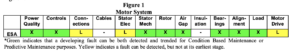
This article discusses three common faults with a PWM drive:
1) An open input diode in the rectifier bridge.
2) Failing capacitors in the intermediate DC circuit.
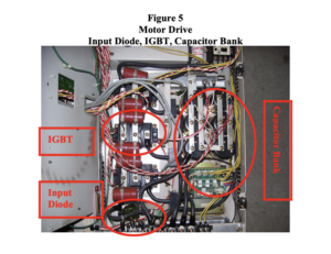
3) Bad Insulated Gate Bipolar Transistor (IGBT).
Of the three, failing capacitors is the most difficult to detect early, as there are no immediate signs of this condition by monitoring the performance of the motor.
About the drive
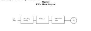
Figure 2 illustrates the basic blocks to a PWM motor drive which include incoming AC power, full-wave diode bridge that rectifies the incoming AC voltage, the intermediate DC circuit that contains the capacitor(s), the inverter bridge and the motor.
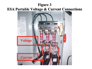
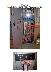
When testing with ESA, voltage and current connections are made to the motor system being tested. This is normally done at the motor control center and connections are made using provided portable voltage probes and portable current transformers or by previously installed special connection boxes. The advantage to the connection box is the ability to take the data without opening up the motor control panel to make these required connections.
With PWM applications two sets of data should be taken, one at the input to the PWM drive and the other at the output of the PWM drive. The entire data collection process (after the connections are made) takes about 4 minutes and no motor nameplate information is required at this point. This information can be entered later when performing the data analysis.
The data files are then viewed using the provided software and a Microsoft® Word report is generated. The software provides easy-to-use tools for working with the different analysis spectra. Software findings can be seen without generating the full report.
The software automatically reports the following:
Power Factor, Current unbalance, Voltage unbalance and RMS voltage to nameplate, Load to nameplate, Phase Connection, Rotor health, Stator electrical and mechanical health, Rotor/Stator air gap, Total Harmonic Distortion (Voltage and Current), Misalignment/Unbalance indications and Bearing health.
It also reports Voltage and Current Peak and Crest Factor, Phase Impedance, Power (Apparent, Real and Reactive), Running Speed, and Line Frequency. For AC induction motors and DC motors it will also calculate motor efficiency.
An average skilled user can run a full analysis and generate a report in less than 10 minutes per motor.
Case One
Case number one is a motor drive that was received at EMA Inc, Cortland, NY service facility. The drive and motor were run on a dynamometer for testing.
Two data sets were collected. The first is a waveform only capture at the input to the drive and then the second set was taken at the output of the drive. The second data set includes a voltage and current waveform capture, plus 50 seconds of voltage and current waveforms.
Figure 6 shows the incoming current waveform for phase C. Note that the negative peaks are missing. This is caused by an open diode.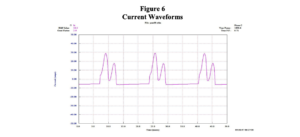
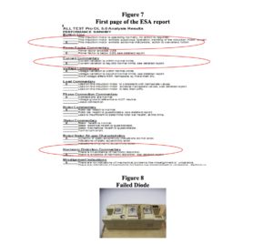
The ESA automatically generated report identifies both Current unbalance and excessive harmonic distortion, which is caused by the open diode.
This first page of the report is a summary only and there are additional pages that provide details for each of the main subject headings. A large current phase unbalance, as seen here, will damage the PWM drive’s internal components and may stress the supply transformer feeding the motor drive
Case Two
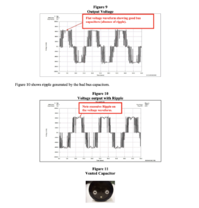
Case number two was received by EMA for repair and involves aging capacitors in the capacitor bank. The problem is as these capacitors begin to age and deteriorate, the performance of the motor will not provide any obvious indications. Once the capacitors begin to fail, additional current is carried by the good capacitors, which create excessive heat in the capacitors, and the additional heat accelerates the failure of the remaining capacitors. These capacitors have vents to dissipate excessive pressure inside, but it is possible for these capacitors to explode, if not vented fast enough. Additionally, the excessive ripple voltage being supplied to the motor will cause harmonic current to be drawn by the motor. These harmonic currents will create negative sequence torque, poor motor performance, and additional damaging heat build up inside the motor.
Figure 9 is showing voltage at the output of the drive and this is for a good drive with capacitors in good condition.
Case Three
Case number three was received by EMA for repair. The output waveform shows an IGBT (Insulated Gate Bipolar Transistor) not turning on. This creates both an unbalance in current and a waveform distortion.
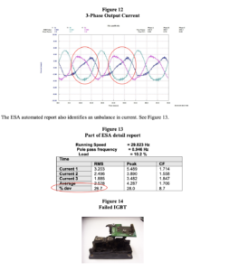
Conclusion
In conclusion, DMM, oscilloscope, and power quality instruments provide good trouble-shooting capability for PWM motor drives. However, they do not integrate well into an electrical motor testing reliability program due to data collection and reporting limitations. Moreover, they provide little information regarding common motor and load related problems.
Electrical Signature Analysis allows the reliability technician to view the entire motor system from incoming power through the driven load. With PWM applications the data collection takes less than 4 minutes after voltage and current connections have been made. From this 4 minute testing process a full 8 analysis can quickly identify problems such as failed rectifier diodes, poor DC bus capacitors, and failed IGBT’s before drive or motor failure has caused the motor system to fail.
It is important to note that in all three cases the motor may still be operating, depending upon load and other operational factors, but the certainty of the system to continue to run is compromised. The ability of ESA to identify these faults early, before additional damage to the motor or the PWM drive occurs, will help minimize expensive downtime, increase equipment reliability, and possibly prevent catastrophic damage to equipment or possible injury to personnel.
About the authors
Richard Scott is the National Sales Manager and Don Haapapuro, CMRP, is the Key Account Manager for ALL-TEST Pro, LLC. ALL-TEST Pro is a manufacturer of portable test equipment for Motor Circuit Analysis (MCA), Electrical Signature Analysis (ESA), and Power Quality Analysis (PQ) used for Predictive Maintenance testing, Quality Control, and Trouble-Shooting of electric motors, generators, transformers, coils and windings. ALLTEST PRO® MCA instruments provide early detection of electrical faults including: winding faults, phase unbalance, rotor faults and ground faults. The ALL-TEST PRO® ESA and PQ instrument provide automatic analysis from incoming power, the electrical motor, through the driven load, both electrical and mechanical. Instruments are handheld, battery operated, easy-to-use and will test virtually any size or type of electrical motor, generator or transformer, even from a remote location. Website is www.alltestpro.com.
Dean Williams is the Vice President of Technical Services for EMA, Inc and he works out of the Cortland, NY service center. EMA sells and services motor drives plus provides training to properly trouble-shoot motor drives. Website is www.emainc.net.
Microsoft® Word is a registered Trademark of Microsoft Corporation.
Copyright © 2008 ALL-TEST Pro, LLC All Rights Reserved
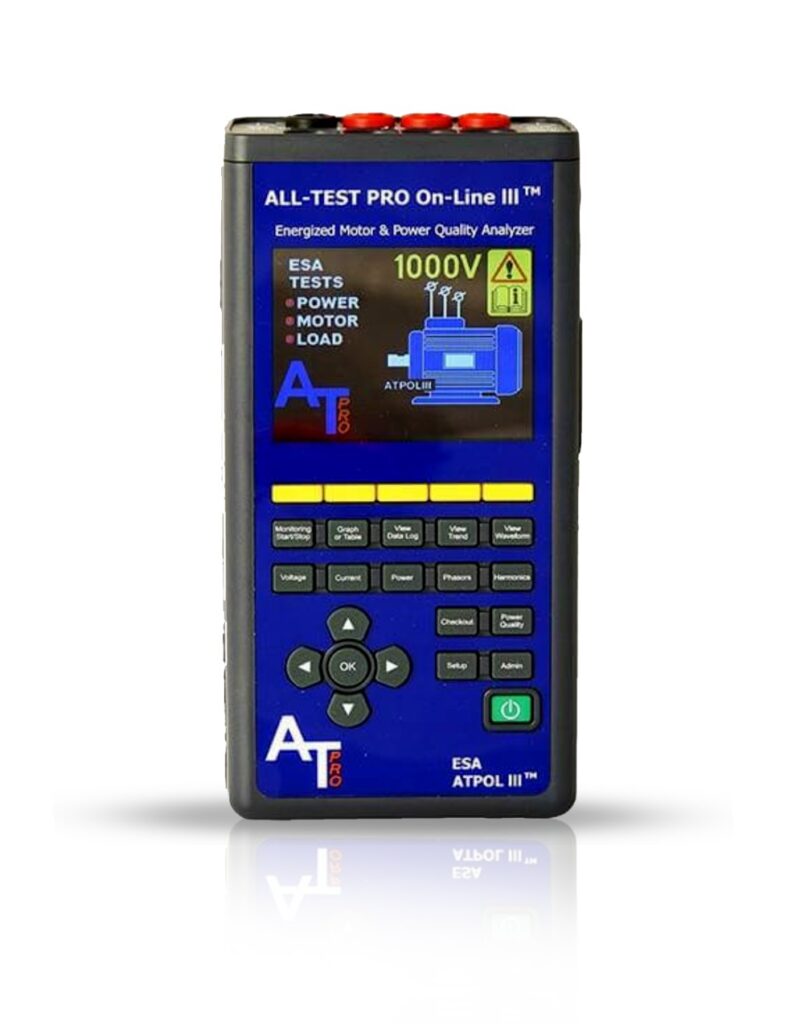
ATPOL III™
Comprehensively analyze power quality and electrical motor component integrity on AC/DC motors, generators, and transformers.

PVT-Hybrid Seminar MCA Level 1 – 08/04/2026-08/06/2026
8:30 am - 5:00 pm PLEASE CONTACT [email protected] AND MENTION REF#125-13896 FOR MORE INFORMATION. First Name * E-mail * Company Phone* Product of Interest* —Please choose an option—AT34EV™AT34™AT7™AT7™ PROFESSIONALATPOL III™MDIII™ALL-SAFE [...]
PVT-Hybrid Seminar ESA Level 1 – 08/11/2026-08/13/2026
8:30am-5:00pm EST PLEASE CONTACT [email protected] AND MENTION REF#125-13889 FOR MORE INFORMATION. First Name * E-mail * Company Phone* Product of Interest* —Please choose an option—AT34EV™AT34™AT7™AT7™ PROFESSIONALATPOL III™MDIII™ALL-SAFE PRO®AccessoriesSoftwareTechnical Support ConsultingOther [...]