WYE ابدأ اختبار DELTA Run Motor باستخدام تحليل دوائر المحرك
Often, when the process has a high inertial load, a six-connector motor will be used as it can be connected in a WYE configuration while starting to limit the current, and then switched to a DELTA configuration automatically by the motor controller once it appears to be accelerating.
Testing in the engine junction box
As with many motors, a simple way to test a six-lead motor involves going directly to the motor junction box. After ensuring all locking/exit marking requirements are met and checking the motor wires for voltage, the motor junction box can be safely opened.
If the motor leads from the controller and the internal motor wires are marked, note this connection. If they are not marked, mark them with colored tape or other identification so they can be reconnected correctly when the test is complete. Disconnect the motor wires from the starter motor, the internal motor wires, or the terminals in the box.
The internal motor wires or terminals should be numbered from one to six. As a check, you should be able to test for electrical continuity between terminals/wires 1-4, 2-5, and 3-6. These are the phase wires (A, B, C, or 1, 2, 3).
To test
the motor using AT IV, you can connect the device to terminals/wires 1-4 for phase 1, terminals/wires 2-5 for phase 2, and terminals/wires 3-6 for phase 3. The INS/grd test must be performed on all three windings individually.
To test the AT33IND or AT5
motor in WYE configuration, you must short-circuit terminals 4, 5, and 6 together. The wires can be joined together or oversized shorting connectors can be used.
The test device(s) can then be connected to terminals/wire numbers 1, 2 and 3. It is necessary to perform only one INS/grd test in this configuration.
Test in the engine control unit
There are several different ways to test a six-lead motor from a motor control unit, depending on the cable size and control cabinet configuration. In the cabinet shown in the image below, using:
ATIV
at the bottom of the RUN and DELTA connectors performs a normal test between 1-4, 2-5, and 3-6. Again, the INS/grd test must be performed for each coil separately.
For AT33IND and AT5,
leads 4, 5, and 6 must be shorted together. This can be done either using jumpers located at the bottom of the DELTA or WYE connectors, or by forcing the WYE connector. With this shorting complete, the device can be connected to cables 1, 2, and 3 at the bottom of the RUN connector.
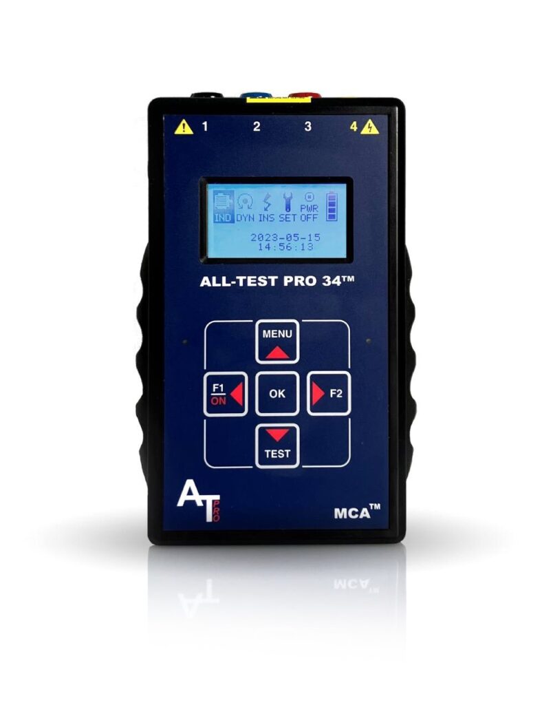
AT34™
قم بتحليل وتوجيه سلامة مكونات المحرك بحثًا عن الأعطال الأرضية، وأخطاء اللف الداخلي، والوصلات المفتوحة، والتلوث – كل ذلك باستخدام جهاز واحد محمول باليد.

ندوة تشخيصية للسيارات من الطراز العالمي عبر الإنترنت – المستوى 1 – من 12 إلى 16 يونيو
هل سمعت؟ سنعقد ندوة تشخيص السيارات العالمية المستوى 1 في الفترة من 12 إلى 16 يونيو . ستكون هذه ندوة عبر الإنترنت / افتراضية تبدأ كل يوم في الساعة 8 […]

Preconlub 15-16 يونيو 2023 ليون ، المكسيك
تعال وانضم إلى المدير الإقليمي لاتام ATP ، جلوريا أوريزار ، كما تقدم في Preconlub 2023! المزيد من التفاصيل: https://www.preconlub.com/ غلوريا اوريزار المدير […]