Motor Circuit Analysis for Energy, Reliability and Production Cost Improvements
Introduction
With news reports quoting power brown-outs due to increased electric demand, methods for controlling energy costs are no longer a green option, but more of a survival strategy. Within industry, the number one potential for energy control is through electric motor system energy strategies.
Electric motor systems use 19% of all energy within the United States, which accounts for 57% of all generated electric power. Over 70% of the electrical energy used by manufacturing, and 90% in process industries, is consumed by motor systems. Electric motor retrofits, variable frequency drive application and other energy efficiency strategies have been receiving encouraging attention. However, two areas that are often overlooked for energy efficiency opportunities are maintenance and reliability.
According to EPRI, The efficiencies of mechanical equipment general can be increased typically 10-15 % by proper maintenance. This includes preventive, predictive, proactive and corrective maintenance programs. In particular, Consistently applied, Motor Circuit Analysis (MCA) can help avoid motor failures, enable proactive maintenance or replacement and improve the energy efficiency of motor systems in general.
Energy costs alone, do not always justify a motor maintenance program. Combined with productivity and associated reliability costs, however, an MCA program can justify itself immediately. Consider, for instance, a 100 horsepower main drive motor for one line of a plant that represents 10% of its overall production, and operates 6,000 hours per year. The plant downtime costs would be $25,000 per hour if 100% of the plant were off line. It would take 6 hours to replace the motor during a catastrophic failure with a startup time of 2 hours. The motor is 75% loaded with energy costs of $0.06/kWh and $14/kW and a 5% impedance unbalance has been detected. The overall increased costs, not including wasted product, would be $24,875 per year. 93.6% would be due to lost production, 3.1% due to increased power consumption, 1.2% due to decreased motor life and 2.1% due to increased demand costs (Figure 1).

Description of Motor Circuit Analysis
The basic concept of MCA is to allow the analyst the opportunity to view the simple resistance (R), complex resistance (Z – impedance), inductance (L), phase angle (power factor), ground insulation condition (Meg-Ohms) and other tests, in order to determine the condition of the electric motor windings. These readings are best obtained, both for safety and accuracy, with the equipment de-energized.
In principle, an electric motor circuit is a series of resistance, both simple and complex, inductance and resulting phase angles that are each 120 degrees apart in a three phase system (Figure 2). When the three phase winding is imperfect, due to original defects or impending failure, based upon the laws of physics, these become unbalanced. In an assembled electric motor, casting voids or broken bars in the rotor, poor air gap or a bowed shaft will cause variations due to the mutual induction between the stator and rotor.
The ability of MCA equipment to read the mutual inductance between the stator and rotor also allows the analyst to detect defects within the rotor or air gap effectively, quickly and safely. Most MCA equipment can operate on motors from fractional to over 10,000 horsepower, 12 volts to over 13.8kV, giving them a broad range of operation, but should not be confused with RCL meters, which provide readings in just resistance, capacitance and induction, usually with a megger or polarization index test added. In addition, high quality MCA units can be purchased for well under $10,000, including software packages, making them a very affordable proactive maintenance tool.
An important distinction between RCL meters and MCA meters is the impedance reading. As current is equal to voltage over impedance, in an alternating current application, voltage and current unbalances are inversely proportional. This provides an important distinction, as a great deal of work has been completed on the economic impacts of voltage unbalance. By using simple resistance, alone, the I2R loss can be determined across a point, but the system reliability cannot be determined, nor can this be done with just inductance, which is variable depending on the winding design and rotor to winding position. Unfortunately, systems using inductance as a base will often fail good electric motors and windings. In order to obtain a true condition of a motor winding, one must view all of the motor circuit components, including resistance, impedance, inductance, phase angle and insulation resistance. At least one manufacturer of MCA equipment adds a special test that doubles the applied frequency and views the resulting ratio between windings. This allows for early detection of turn to turn and coil to coil faults that would, otherwise, go undetected.
The Energy Impact of MCA
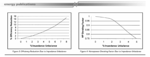
The purpose of an electric motor is to convert electrical energy to mechanical torque. It operates best when all three phases are 120 degrees from each other and other stator, rotor and friction losses are controlled. As the phases vary 120 degrees from each other, the efficiency of the motor decreases because it becomes harder for the magnetic fields to turn the rotor. When far enough off, they begin to interfere with each other. This effect can be found in both voltage and impedance unbalances, including the impacts to efficiency, reliability and production. As with voltage unbalance, 1-2% unbalance is acceptable, but unbalances should not exceed 5% as the temperature rise increase will exceed 50% at that point. When the impedance unbalance exceeds 2%, the motor should be derated as shown in Figure 4.
One important impact of impedance unbalance is energy efficiency and the associated cost impacts. The simple energy calculations for electric motor efficiency are as follows:
Equation 1:
kW LossesKW = hp * .746 * load * [(100/E1) – (100/E2)]
Where: hp is horsepower, E1 is the new efficiency, and E2 is the original efficiency
Equation 2:
Demand Costs $kW/year = $/kW * kW * 12 months/year
Equation 3:
Energy Usage Costs $kWh/year = $/kWh * hours / year * kW
The efficiency impacts of impedance unbalance can be found in Figure 3. A 50 horsepower energy efficient electric motor, 1800 RPM, 95% efficient, 85% loaded, operating for 6000 hours per year, with a 3.5% impedance unbalance would have a resulting efficiency of 91%. With an average energy cost of $0.06/kWh and average demand cost of $14/kW, the resulting energy costs would be as follows:
Example 1: 50 Horsepower Motor with 3.5% Impedance Unbalance
50 hp * .746 * .85 * [(100/91) – (100/95)] = 1.47 kW
$14/kW * 1.47 kW / month * 12 months / year = $246.96 / year
$0.06 / kWh * 6000 hours / year * 1.47 kW = $529.20 / year
Total Annual Energy Costs = $776.16 / year
The annual increase in energy costs for operating this motor is significant. Impedance unbalance effects within a plant become even more significant as additional electric motors are found. Along with the decrease in efficiency, electric motor system reliability and production are affected.
The Reliability Impact of MCA
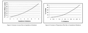
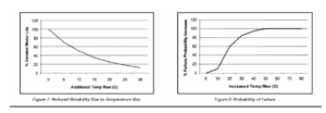
The Reliability Impact of MCA As a direct result of impedance unbalance, the operating temperature of the electric motor will increase, as well as electro-mechanical stresses within the motor winding and rotor. The increase in losses can be found in Figure 5, with the impact on operating temperature found in Figure 6, and the motor reliability reduction in Figure 7. It is important to understand that determining a phase unbalance or potential winding failure will not allow you to predict an electric motor failure. Testing can be tracked and trended in order to determine the point where the reliability, or confidence that the motor will operate as designed, will be reduced to a point where the owner will determine that the motor should be repaired or replaced. This point should be fairly tolerant for non-critical motors and have a low tolerance for critical equipment.
The same 50 horsepower motor with a 3.5% impedance unbalance would have the following reliability losses:
Increases in losses of 20%.
A 25% increase in temperature rise. For a motor rated as 40oC ambient, Class F insulation, operating in a 22oC environment, the normal temperature rise at 85% load would be 80oC. The 25% increase would make the new temperature rise to 100C a 20oC temperature increase.
The 20 temperature increase would reduce the potential life of the electric motor to 25% of its original potential (the life of insulation decreases by half for every 10oC increase in temperature). This does not include any other potential impact on the insulation system or turn insulation system.
Production Impact of MCA Testing
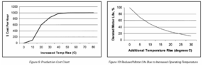
The direct impact on production of the combined increase in energy costs and reduced reliability will depend on how critical the motor is to operations. For instance, the main drive of a production line will be very critical, while an air-handling unit may have a minimal impact on production. With the increase in probability of failure, an estimated cost to production can be established. This production cost estimate can be determined per $1,000 per hour against Figure 9 by factoring in how much of production will be affected and the potential downtime and startup time, should the motor fail unexpectedly.
The 50 horsepower electric motor with the 3.5% impedance unbalance would have a 60% chance of failure and $600 / $1000 in potential production losses. Therefore, should the 50 horsepower be a critical electric motor that has a 100% impact on a $5000 per hour line, with a 4 hour downtime and 1 hour start-up time, the impact cost would be a potential loss of $15,000:
Equation 4: Production Losses
$600/$1000 * $5000 * 4 hours * 1 hour = $15,000 lost production
Bringing It All Together In the example used through the article, a critical 50 horsepower electric motor with a 3.5% impedance unbalance was used. The total potential costs associated with this impedance unbalance will be:
![]()
This motor would be a candidate for repair or replacement in order to avoid potential costs. If the motor is removed and replaced during the next shutdown:
Replacement of a 95% efficient electric motor cost: $2,250
Replacement labor: $500
Original MCA test equipment cost: $7,995
Test labor (5 minutes at $60/hour): $5
Total: $10,750
Simple payback: 0.68 years or 8 month simple payback
Not including the test equipment cost: 0.17 years or 2 months
A reliability check on the new motor should be performed when it arrives at the plant to ensure that there are no manufacturing defects.
Conclusion
Motor Circuit Analysis is a powerful tool that is simple and intrinsically safe (offline test). The testing range and potential payback is almost immediate. The example used within this article represents only one motor in a plant. Should an analysis determine additional electric motors that require attention, the original purchase and implementation of the MCA program, when combining energy and production costs, will be immediate. Implementing such a program as an in-house program or service is straight-forward:
MCA Training – most systems require no more than 1 to 8 hours of in-house training for basic operation with a reasonable usage learning curve for advanced analysis
Determine critical motors – motors that are critical to operation
Perform analysis on selected motors and determine results
Track and trend critical motors at least quarterly, monthly if possible
Implement opportunities
Increase scope of testing based upon success
The results of the MCA program, in combination with other proactive maintenance systems, will yield excellent results in energy savings, reliability improvements and production uptime.
Bibliography
Sarma, Mulukutla S., Electric Machines: Steady-State Theory and Dynamic Performance, PWS Publishing Company, 1994.
Nasar, SyedA.,TheoryandProblemsofElectricMachinesandElectromechanics,SchaumsOutlineSeries,1981.
Edminster, Joseph, et.al., Electric Circuits Third Edition, Schaums Electronic Tutor, 1997.
Hammond, et.al., Engineering Electromagnetism, Physical Processes and Computation, Oxford Science Publications, 1994.
Penrose, Howard W., Repair Specification for Low Voltage Polyphase Induction Motors Intended for PWM Inverter Application, Kennedy-Western University, 1995.
Penrose, Howard W., A Novel Approach to Total Motor System Maintenance and Management for Improved Uptime and Energy Costs in Commercial and Industrial Facilities, Kennedy-Western University, 1997.
Penrose, Howard W., A Novel Approach to Industrial Assessments for Improved Energy, Waste Stream, Process and Reliability, Kennedy-Western University, 1999.
Penrose, Howard W., Anatomy of an Energy Efficient Electric Motor Repair, Electrical Insulation Magazine, January/February 1997.
Phase Frame Analysis of the Effects of Voltage Unbalance On Induction Machines, IEEE Transactions on Industrial Applications, Vol. 33, No. 2, Mar/Apr 1997, p. 415.
Bonnett, Austin A., How to Analyze Rotor and Stator Failures for Three-Phase Squirrel Cage Induction Motors, EASA Conference, 1997.
Varatharasa, Logan, et.al., Simulation of Three-Phase Induction Motor Performance During Faults, EIC/EMCW Conference 1998 CD Rom.
US Department of Energy, et.al., Keeping the Spark in Your Electrical System, US DOE, October, 1995.
About the Author
Dr. Howard W. Penrose, Ph.D. has over 15 years in the electric motor and electric motor repair industry. Starting as an electric motor repair journeyman in the US Navy to field service and evaluation of small through large rotating equipment of all types, as the Chief Engineer of a large Midwestern motor repair shop. Dr. Penrose has been directly involved in rewinding, training and troubleshooting AC, DC, wound rotor, synchronous, machine tool, and specialty equipment. His. further studies involve electric motor and industrial reliability, test methods, energy efficiency and maintenance impact on production. Dr. Penrose is a past Chair of the Chicago Section of IEEE, a past Chair of Dielectrics and Electrical Insulation Society of IEEE Chicago, a Professional Member of the Electrical Manufacturing Coil and Winding Association, a US Department of Energy Certified Motor Master Professional, a Vibration Analyst, Infrared Analyst and Motor Circuit Analyst.
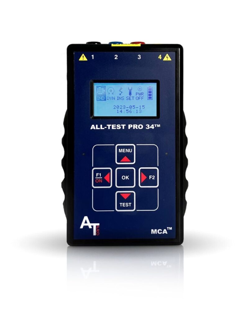
AT34™
Analyze and trend motor component integrity for ground faults, internal winding faults, open connections, and contamination – all with one hand-held device.

PVT-Hybrid ESA Level 1 — 6/09/2026-6/11/2026
8:30 AM-5:00 PM PLEASE CONTACT [email protected] AND MENTION CASE #125-13768 FOR MORE INFORMATION.

Virtual Orientation — 6/19/2026
1:00PM-2:00PM EST PLEASE CONTACT [email protected] AND MENTION CASE #125-13887 FOR MORE INFORMATION. First Name * E-mail * Company Phone* Product of Interest* —Please choose an option—AT34EV™AT34™AT7™AT7™ PROFESSIONALATPOL III™MDIII™ALL-SAFE PRO®AccessoriesSoftwareTechnical Support [...]